Home › Unlabelled ›
Relay Driver Circuit Using Transistor - Arduino Relay Control Tutorial With Code And Circuit Diagram / The coil of relay needs a current about 100 ma.
Relay Driver Circuit Using Transistor - Arduino Relay Control Tutorial With Code And Circuit Diagram / The coil of relay needs a current about 100 ma.. I will build tonight hopefully. The value of the 1k resistor and electrolytic can be adjusted to suit individual. Designing transistor biasing circuits using qbasic. This article discusses about relay driver circuit using uln2003. Transistor as a relay driver.
Basic driver circuit using a bjt transistor. In the circuit below is most transistor relay driver circuit. As +5 v reaches 2.5 v, the cpld output goes to logic zero. I will return with the results and final diagram to share. When the circumstances make the use of this connection unavoidable, if the voltage is not completely impressed on the relay, the transistor does not conduct completely and operation is.
Transistor Relay Driver Circuit In Digital Eleccircuit Com from www.eleccircuit.com This article discusses about relay driver circuit using uln2003. We must need an external circuit to drive relays with stm32 microcontrollers. But sometimes it is required to switch larger relay coils or currents beyond the range of a bc109 general purpose transistor and this can be achieved using darlington transistors. Understand the relay circuit using uln2003 ic. I am sure with using a op amp circuit i will be fine. The coil of relay needs a current about 100 ma. Pnp, npn, or mos transistors can also be used. In this video, 5v relay trigger circuit using 5v digital signal, i've explained how to make an optically isolated relay driver circuit by.
The transistor is a 2n2222a the relay a 5 volt axicom d3009 with 30.1 ma coil draw.
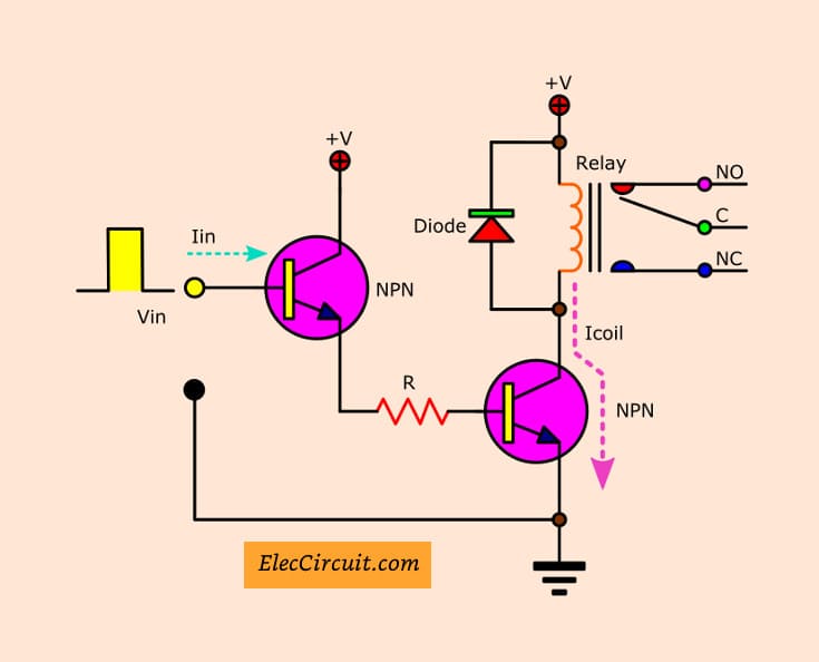
Designing transistor biasing circuits using qbasic. I am sure with using a op amp circuit i will be fine. Pnp, npn, or mos transistors can also be used. Basic driver circuit using a bjt transistor. Understand the relay circuit using uln2003 ic. In this transistor circuits ebook, we have presented about 100 interesting circuits using transistors and chips. But sometimes it is required to switch larger relay coils or currents beyond the range of a bc109 general purpose transistor and this can be achieved using darlington transistors. How to make a simple relay circuit | relay driver using transistor подробнее. Transistor relay driver circuit schematic. The uln2803 ic consists of eight npn darlington pair which provides the proper current amplification required by the loads. Here the ground refers to the negative line for an npn and the positive line for a pnp. Learn how transistors work and how they are used as switches in simple circuits. On inductive loads (i.e., motors, relays, solenoids), a diode is often connected.
Table of contents why do we need to use relay driver circuits? Now that we're using a transistor to drive. One more thing one can do with an npn transistor is use it as a relay. The previous npn transistor relay switch circuit is ideal for switching small loads such as led's and miniature relays. The uln2803 ic consists of eight npn darlington pair which provides the proper current amplification required by the loads.
Results Page 12 About Opto Isolation Driver Searching Circuits At Next Gr from www.next.gr I found this circuit for a relay driver. Another 470uf capacitor is added parallel to the relay coil which maintains steady current through the relay coil so that relay clicking can be avoided if the power supply varies momentarily. The coil of relay needs a current about 100 ma. We must need an external circuit to drive relays with stm32 microcontrollers. Electronics tutorial about the relay switch circuit and relay switching circuits used to control a variety of loads in circuit switching applications. Start date mar 4, 2013. This website uses cookies to improve your experience. Table of contents why do we need to use relay driver circuits?
Pnp, npn, or mos transistors can also be used.
In the circuit below is most transistor relay driver circuit. We have previously used easyeda many times and found it very convenient to use compared to other pcb fabricators. The previous npn transistor relay switch circuit is ideal for switching small loads such as led's and miniature relays. The resistor used on the base of the transistor is typically around 1k ohm. Relay transistor fan relay coil driver this robust driver interfaces a dc , driver with demagnetizing diode one 100 ma magnetron relay coil driver with abstract: The coil of relay needs a current about 100 ma. Here the ground refers to the negative line for an npn and the positive line for a pnp. This article discusses about relay driver circuit using uln2003. Transistors are best suitable with microcontrollers for driving relays. The uln2803 ic consists of eight npn darlington pair which provides the proper current amplification required by the loads. Transistor relay driver circuit schematic. The value of the 1k resistor and electrolytic can be adjusted to suit individual. The transistor primarily provides current gain.
In this instructable you will make a transistor relay driver. The coil of relay needs a current about 100 ma. The advantages of bjts over mosfet transistors are being able to handle a high range of input voltages due to rb resistor without failing. I am sure with using a op amp circuit i will be fine. The resistor used on the base of the transistor is typically around 1k ohm.
Lab Iii Voltage Comparator And Relay Drivers By Using Bjts Kmitl58010911 from sites.google.com In this transistor circuits ebook, we have presented about 100 interesting circuits using transistors and chips. As +5 v reaches 2.5 v, the cpld output goes to logic zero. Basic driver circuit using a bjt transistor. Relay driver circuit is a switch that is used in low voltage circuit to switch a light bulb on and off. But sometimes it is required to switch larger relay coils or currents beyond the range of a bc109 general purpose transistor and this can be achieved using darlington transistors. One more thing one can do with an npn transistor is use it as a relay. Because this circuit contains a transistor, much less power needs to used on the input side to drive it. Another 470uf capacitor is added parallel to the relay coil which maintains steady current through the relay coil so that relay clicking can be avoided if the power supply varies momentarily.
Relay driver circuit is a switch that is used in low voltage circuit to switch a light bulb on and off.
How to make a simple relay circuit | relay driver using transistor подробнее. Here the ground refers to the negative line for an npn and the positive line for a pnp. Relay driver circuit is used to drive the relays and interface relays with other circuitry. Relay driver ic uln2003 pin diagram. Relay driver circuit is a switch that is used in low voltage circuit to switch a light bulb on and off. Transistors are best suitable with microcontrollers for driving relays. Using a diode plus resistor, zener in series with a diode, or zener across the transistor (tvs may take the place of a zener diode) can allow the relay coil voltage to rise higher, hastening the collapse of the magnetic field (but harder on the transistor). Pnp, npn, or mos transistors can also be used. When the switch is open no base current flows, so the transistor switches off the collector current. You can build this circuit with two standard 5mm red leds and any general purpose low power npn. The circuit we will build is shown below: A relay driver circuit is a circuit which can drive, or operate, a relay so that it can function because this circuit contains a transistor, much less power needs to used on the input side to drive it. The relay in this circuit will remain active for a few seconds after the push button has been released.